A Sixth Sense – the science behind Migraines with Aura

Standard

So Much More Than ‘Just A Headache’

Unfamiliar with the extreme pain a migraine brings, it’s natural to try and relate it to a bad headache – mistaking the condition’s throbbing pain for a common distracting ache. Besides intense pain, migraines also come with a host of sensory issues such as severe sensitivity to sound and light (known as photophobia), neck stiffness, and visual phenomena. While headaches are an infamous symptom of illness, migraines are the illness.

The most striking difference between a migraine and a headache is that, almost as if they have a sixth sense, one in three migraine sufferers can predict when one is brewing before the pain sets in. Relax – we’re not omniscient. In the build up to a migraine attack, we experience auras: transient visual disturbances that are as disorientating as they are fascinating from a scientific perspective.

What starts out as a shimmering haze in the migraine sufferer’s periphery, gradually envelops their field of vision with flashing lights, shimmering arcs, and blind spots. Although auras serve as a warning for an impending migraine attack, they can be far more dangerous than the ensuing headache; during auras, brain cells can become damaged, even to the point of death, causing ischaemic strokes and creating lesions in the white matter of the brain. But what’s the connection between a migraine and these strange visual symptoms?

Origin of an Aura

At the onset of a migraine, the biochemistry of the brain changes drastically. At rest, healthy neurons contain fewer positively charged ions such as sodium ions (Na+) and potassium ions (K+) and more negatively charged proteins and nucleic acids than their surroundings. This separation of charge gives their membranes a low resting potential of -70 mV.

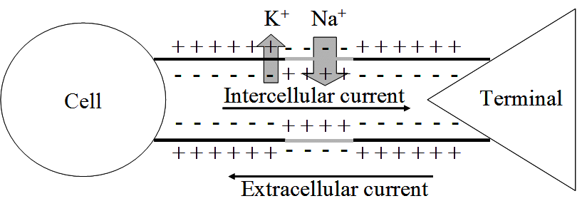
If we compare a neuron’s axon to a simple tube connecting one neuron to its neighbour, we can see that the inside of the axon is more negative than its surroundings outside the cell (the extracellular space).

Triggering the migraine aura is a sudden, spontaneous efflux of K+ ions out of a single neuron buried deep in the brain’s visual cortex – causing the cell’s membrane potential to plummet. The build-up of K+ ions in the extracellular space triggers the release of amino acid glutamate which excites neighbouring neurons and allows K+ ions to flood in – propagating the ion movement further. On the heels of this sudden flurry of activity, comes a wave of neuronal silence in which each cell stops processing and transferring information as it slowly returns to normal.

This wave of intense excitement followed by inactivity spreads across the visual cortex – corrupting visual information from the eyes and creating strange auras.

This phenomenon, known as cortical spreading depression (CSD), is responsible for the peculiar auras that slowly take over a migraineur’s visual field. When a neuron is affected by the spreading depression, it stops accurately processing visual information from the eyes – instead interpreting signals into disturbances like flashing lights or blurry blind spots.

The gradual spread of CSD across the visual cortex is mirrored by the gradual growth of an aura in the build up to a migraine attack.

Cortical spreading depression is not unique to the visual cortex; it can occur throughout the grey matter. The reason why this wave of electrical activity originates in the visual cortex is because this region of the brain is very densely crammed with neurons – increasing the risk of one neuron’s aberrant activity affecting the many cells around it.

CSD & Pain

The effects of CSD extend far beyond interfering with vision. Neuron excitation in the visual cortex activates adjacent trigeminal nerves which span your face from temple to jaw. These nerves run parallel to major blood vessels of the meninges (the cushioning tissue between your skull and brain) and, when activated, trigger the release of pain-generating substances into the bloodstream. As a result, the meninges become inflamed, causing blood vessels to widen and put further pressure on the tissue – intensifying the pain.

To make matters worse, these waves of neural activity up-regulate the expression of genes encoding pro-inflammatory molecules (such as COX-2, the target of many painkillers) exacerbating the sensation of pain. Additionally, CSD activates metalloproteinases, provoking the blood-brain barrier to leak; pro-inflammatory molecules, as well as the K+ and glutamate from earlier, are now free to flood into the major facial blood vessels. In combination, these molecules sensitise the nerves in the neck and jaw, causing the notorious aches and stiffness many migraine sufferers endure. This sensitisation is also why normally innocuous processes (like coughing and yawning) hurt and cause tension to build up during a migraine.

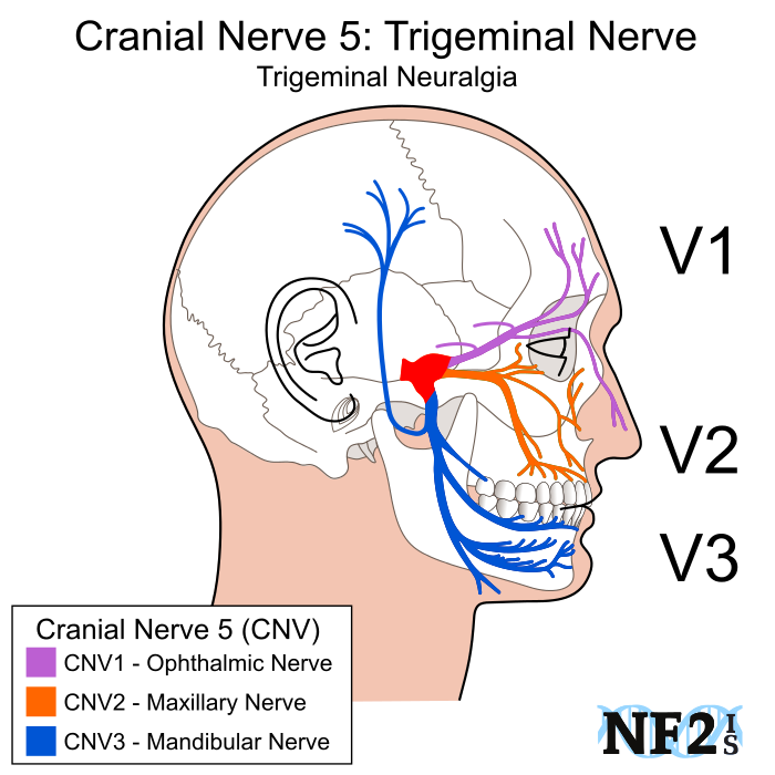
The spreading depression is first transmitted to the ophthalmic nerve branch and is then propagated to the mandibular nerves, bringing the pain along with it.

Potential Treatments

None of these excruciating effects are felt in ordinary headaches where CSD plays no role; to reiterate, the intense pain felt by migraine sufferers comes down to the unique biology of a migraine attack – it has nothing to do with low pain thresholds and its far more than just a bad headache.

Currently, the majority of migraine treatments either suppress pro-inflammatory molecule production or tackle the excessive blood vessel widening which puts pressure on the meninges. While they are useful in dealing with the headache aspect of a migraine attack, they have no effect on auras and fail to address the root cause of the migraine: the CSD.

Drugs that interfere with dopamine and serotonin pathways have been proven effective, quite possibly because they control neurotransmitter release and hence limit excitation of adjacent neurons in CSD – curbing the spread of depolarisation. Potential novel treatments also address the K+ ion channel dysfunction that triggers CSD, preventing both the aura and the pain that follows it.

When it comes to migraine treatment, the classic proverb rings true – prevention is better than cure. However, there are shockingly few effective migraine prophylactics.
Research into what triggers the K+ ion efflux of CSD in the first place and why sufferers are genetically predisposed to having migraines could spare the nearly 10 million of us in the UK from frequent bouts of agony.

.

Bibliography:

  • Pietrobon, D., Striessnig, J. Neurobiology of migraine. Nat Rev Neurosci 4, 386–398 (2003). https://doi.org/10.1038/nrn1102
  • Lauritzen, M. (1987). Cortical spreading depression as a putative migraine mechanism. Trends in Neurosciences, 10(1), 8–13. doi:10.1016/0166-2236(87)90115-9 
  • Charles, A. C., & Baca, S. M. (2013). Cortical spreading depression and migraine. Nature Reviews Neurology, 9(11), 637–644. doi:10.1038/nrneurol.2013.192 
  • Medscape.com. (2019). Migraine Headache: Practice Essentials, Background, Pathophysiology. [online] Available at: https://emedicine.medscape.com/article/1142556-overview#a3.
  • Spierings, E. L. H. (2001). MECHANISM OF MIGRAINE AND ACTION OF ANTIMIGRAINE MEDICATIONS*. Medical Clinics of North America, 85(4), 943–958. doi:10.1016/s0025-7125(05)70352-7 

I’ve written this post for Migraine Awareness Week – if you wish to support research into treatments for this debilitating neurological condition, consider donating to Brain Research UK.

The Most Important Race of Your Life

Standard

Before the first cells of our bodies are even formed, we all owe our lives to electricity. It plays a crucial role in the first and most important race of our lives, regardless of whether we grow up to be marathon runners. This is the race of fertilisation, in which the finish line is an egg cell and the winner is the sperm cell that made each one of us.

In the same way that professional athletes have light, aerodynamic bodies and strong legs to propel them, sperm cells are streamlined and specialised to win their race. But instead of powering their movement with muscular limbs, sperm cells have powerful tails, known as flagella, which beat from side to side, tunnelling their way through the viscous fluid of the female reproductive tract.

At first, the race is akin to a marathon in which covering the distance between the vaginal opening and the uterus, without running out of energy, is the main priority. Dyenins, molecular motors embedded in the base of the flagella, produce a rapid symmetrical bending movement which quickly move the sperm cells to the upper reproductive tract in under half an hour.

From Ions to Energy
Just like the motors which keep the blades of ceiling fans spinning, these molecular motors need a constant supply of energy to keep the flagella beating. This energy comes in the form of tiny molecules called ATP which are continuously pumped out of miniature factories known as mitochondria. Mitochondria are bean-shaped organelles which have two membranes – an outer membrane which covers the organelle like a skin and a highly-folded inner membrane keeps important chemicals inside the organelle. There are mitochondria in all the cells in our bodies, but sperm cells need so much ATP to swim all the way to the egg that they are absolutely brimming with them. To produce all that ATP, mitochondria themselves require electrical energy.

So how do they get this electrical energy? First, let’s quickly return to our analogy of the ceiling fan, which uses electrical energy directly. Flick the switch on and extremely tiny charged particles flow through the wires of the fan motor. Electricity is really just the flow of any charged particle; when electricity flows, energy transfers along with it. The device you are reading this on is powered by the flow of negatively charged electrons. Our bodies, on the other hand, are mainly driven by slightly larger, positively charged particles: ions.

Our mitochondria are extra special because they can make use of both ions and electrons. First, these miniature factories shuttle around electrons to create flows of charge: bioelectricity. The resulting energy transfer is used to push positively charged hydrogen ions (H+) out of the mitochondrial inner membrane into the empty space between membranes. This causes a build-up of H+ ions on one side of the inner membrane and a loss of H+ ions on the other side. This results in one side of the inner membrane being more positively charged than the other – creating an electrical potential gradient (aka a voltage).

As I write this article, my abandoned cup of piping-hot tea is quickly turning cold; in the same way that heat tends to flow from a hot object to the cold surrounding air, charged particles tend to move from a positively charged area to a negatively charged one, down to the electric potential gradient. H+ ions in the mitochondria’s intermembrane space try to squeeze back through the inner membrane to the more negatively charged side.

But biological membranes repel H+ ions because they are charged so the ions cannot pass through freely. Mitochondria take advantage of that fact by having lots of specialised ion channels embedded in their inner membrane; these channels allow H+ ions to easily diffuse through to the more negatively charged side. But there is a catch. As H+ ions flow through the specialised channels, their electrical potential energy is transferred to the channel and used to manufacture more ATP!

We have now seen two ways sperm use bioelectricity, in their mitochondria, to help spin their flagella. Bioelectricity is essential for the repetitive side-to-side beating needed to get the sperm to the uterus. But the sperm cell’s journey doesn’t end there…

A Sticky Situation
When a sperm cell draws nearer to the egg cell, its marathon transforms into an obstacle course. Before it can even begin to navigate the sharp turns and swooping bends of the fallopian tubes, the sperm gets trapped by spindly finger-like projections at the tube entrance.

To free itself from the clutches of the upper reproductive tract, a change of movement is required. Sperm cells don’t have another type of molecular motor which takes over the flagella, but they do have a trick up their metaphorical sleeves, and this too involves bioelectricity.

As the sperm cell travels through the uterus, the environment changes. Earlier, the cell journeyed through a mixture of seminal and cervical fluid. Now, as it reaches the fallopian tube, it must swim through the sticky fluid released by the ovaries. Known as follicular fluid, this stuff is far richer in positively charged sodium (Na+) ions than the sperm cell’s cytoplasm. As a result, there’ is an imbalance of charge between the inside and outside of the sperm cell: a voltage .

This voltage triggers the opening of specialised exchanger proteins in the sperm cell membrane which can trade sodium ions outside the cell for hydrogen ions within the cell. As the sperm cell pumps out H+ ions through this exchanger, the concentration of H+ ions rapidly plummets. The pH of the cell’s cytoplasm is inversely proportional to H+ concentration; as the ion concentrations decreases, pH increases – making the cytoplasm more alkaline. This is crucial for initiating the next phase of sperm movement.

Modifying Movement

While the sperm cell is still held hostage by the spindly projections of the fallopian tube, it gets bathed in even more follicular fluid, which is rich in the hormone progesterone. Sperm cells are highly receptive to even a trillionth of an increase in progesterone concentration, so this flood of hormone induces great changes in its behaviour.

In combination with the alkaline environment, progesterone triggers the opening of CatSper channels (Cationic channels of Sperm) which allow positively charged calcium ions to flood into the sperm, yet again modifying the voltage across the sperm cell membrane.

More importantly, these calcium ions influence the dyenins in sperm flagella, so they produce an asymmetrical, whip-like movement. Adding calcium ions is akin to adding gears between the motor and the wheels of a car when you need more power to drive up a steep hill. The Ca2+ ions slow down the molecular motors and increases the overall bending of the flagella so that each beat of the sperm’s tail is more forceful. With this extra power, sperm cells can kick away from the clutches of the fallopian tube entrance. The asymmetric movement, combined with the sperm cell’s attraction to progesterone, allow it to steer a course towards the egg cell.

Bioelectricity, in the form of changing voltages and positive charge flow, is vital for sperm cells to break free from the microvilli projections at the entrance and make that final push through the fallopian tubes to the finish line of fertilisation. Staggeringly few sperm cells make it. Only one sperm cell out of every million that enter the female reproductive tract even makes it to the fallopian tube and less than a hundred ever come close to the egg. To put this in context, a healthy man can ejaculate about a teaspoon of semen, teeming with 500 million sperm cells – each sperm has a shockingly slim 0.00002% chance of even meeting the egg.

Without the powerful whipping motion that this bioelectricity enables, sperm cells can’t fertilise an egg cell and so a male cannot transfer genetic material to produce offspring. Ultimately, bioelectricity issues can result in infertility, a condition that affects 7 in 10 British couples.

Polyspermery: It’s A Draw
The converse issue, wherein lots of sperm cells are very efficient swimmers and reach the egg cell at the exact same time, also hinders reproduction. In a phenomenon known as polyspermy, two or more sperm cells fertilise the egg cell at the same. In terms of our race metaphor, polyspermy happens when two competing sperm cells ‘draw’ and there is no winner.

An egg cell fertilised by two or more sperm cells cannot divide the contributed genes evenly to split into new cells and produce an embryo, so the fertilised cell dies. As we’ll see shortly, polyspermy isn’t a major threat for humans since multiple sperm cells rarely reach the egg at the exact same instant. However, the risk of polyspermy is a serious issue for many marine animals that rely on external fertilisation to form offspring.

Sea Urchin Sex
Consider sea urchins, probably the spikiest creatures beneath the waves. Male and female sea urchins reproduce by releasing clouds of sperm and egg cells into the water and hoping they fuse to form offspring larvae. Compared to humans, many more sea urchin sperm cells approach a single egg simultaneously. To prevent polyspermy, a fertilised egg cell needs to act fast and block access to any more competitor sperm. This calls for bioelectricity.

An urchin egg cell waiting to be fertilised contains fewer positively charged ions than the surrounding seawater. This disparity in positive charge between its internal and external environment create a voltage known as a membrane potential; in the case of an unfertilised sea urchin egg cell, this membrane potential is -70 mV.

The very instant that the first sperm cell, the winner of the fertilisation race, binds to the egg cell, it triggers calcium and sodium ion channels to open and allow the positively charged ions to flood in. This results in a reversal of membrane potential as the inside of the egg cell becomes more positive than its surroundings, depolarising the membrane to +25 mV.

This rapid switch in membrane charge inhibits additional sperm cells from binding, however the exact mechanism remains a mystery. One prevailing theory is that a positive membrane potential inactivates the specialised slots in the egg cell membrane that allow sperm cells to dock in – preventing additional sperm from fusing with an already fertilised egg.

Alternatively, the positively charged proteins on the tip of the sperm cell, which fuse it to an egg, might be repelled by the newly positive membrane of the egg cell, ultimately inhibiting fusion and polyspermy. Regardless of the true mechanism, it is evident that bioelectricity plays an important role in guaranteeing successful fertilisation, and not only in sea urchins.

Slow Blocks
Polyspermy is not as immediate a threat to fertilisation for humans due to the relatively low sperm-to-egg ratio and the complexities of navigating the female reproductive tract. Instead of a fast, electrical block, our fertilised egg cells block out additional sperm through chemical methods: a slow block . To understand how human egg cells do this, we need to first look at its structure and its vulnerability to polyspermy.

Like all body cells, egg cells have a standard membrane that keeps all its cellular machinery and DNA inside, safe and secure. On top of this, egg cells are coated in a transparent jelly layer called the zona pellucida, which allows sperm cells to tether to the egg during fertilisation. The slow block to polyspermy involves changes in both the inner membrane and the zona pellucida.

Within minutes of fertilisation, the ‘winning’ sperm triggers calcium ions from within the egg cell to be released from their storage spaces and rush through the cell membrane. But unlike in the sea urchin eggs, this ion movement is not a one-time event for human egg cells. In the next minute, another wave of positively charged ions are sent out, and this whole process is repeated over and over and over. The end result is the formation of a fluctuating membrane potential which steadily flicks from positive to negative like a metronome.

These calcium ion oscillations themselves do not deter additional sperm. Instead, they orchestrate a cascade of reactions which trigger little pockets of enzymes to be pushed out of the egg cell. The enzymes inside can then dissolve the bonds between the membrane and the zona pellucida, pushing away the jelly layer and all the other attached competitor sperm cells along with it.

An IVF Issue
For natural human conception, this slow block is sufficient. However, within the last fifty years, this process has been unable to keep up with a novel form of reproduction we have pioneered: in vitro fertilisation (IVF). The conditions of IVF are very different to that of natural conception – the reproductive tract with its pH gradient, microvilli obstacles and sharp bend is swapped out for a simple laboratory dish. Many more sperm cell are incubated with a single egg to increase the chance of successful fertilisation. The consequence is that, when the playing field for sperm is levelled to this extent, the classic slow block might not act fast enough to block out additional sperm cells. Up to 10% of fertilised eggs in IVF become non-viable due to polyspermy.

Recent studies suggest that egg cell quality could influence polyspermy block speed. By studying our rodent friends, biochemists have found that older mice eggs are more likely to have abnormal calcium signalling. The oscillations are irregular, like a broken metronome swaying wildly out of time. As a result, not enough enzyme pockets are recruited to the membrane. This means that the zona pellucida does not completely detach from the egg cell – allowing some sperm cells to stay stuck in place and squeeze inside.

Moreover, the in vitro setting and egg freezing involved in IVF decrease both the frequency and duration of calcium ion oscillations. Whilst screening eggs for their quality is still out of reach, bioelectricity research could improve egg preservation techniques – bringing the finish line closer in the most important race of our lives.

Return to the Stamataki Lab

Standard

I’ve kicked off this summer with a trip to Birmingham to meet with Dr Zania Stamataki. During my prior work experience here, I improved my wet lab skills by learning essential techniques such as splitting cell lines, performing serial dilutions, and imaging plates with confocal microscopy.  This year, I chose to hone my computational biology skills to best prepare me for a future in research; Dr Scott Davies introduced me to bioimage informatics through training me to work with the ZEISS Efficient Navigation (ZEN) microscopy software.

The ZEN software can be used to process the plethora of data that a single imaged experiment can yield. I worked with data from an experiment in which Huh-7 hepatocytes (from an immortalised liver carcinoma cell line) are co-cultured with live T-cells and imaged using confocal microscopy.


I personally found this sophisticated mode of imaging fascinating so I did a little more research into the bioengineering responsible for the high resolution and vibrancy of the  cellular interactions captured by the confocal microscope. Unlike the humble optical microscopes of my school, which only need light and a pair of eyes to visualise cells, confocal microscopes require far more exotic elements: lasers and fluorescent dyes.


1gfl

GFP

One of the most widely used fluorescent biomarkers is green fluorescent protein (GFP) which is used in this experiment to highlight the cell membranes. GFP is a very important tool in research as it enables us to look beyond the cell surface and visualise organelles and protein movements. GFP has a unique sequence of the amino acids serine, tyrosine, and glycine which can be triggered to undergo chemical transformations in the presence of UV light. This special amino acid sequence is buried deep within the molecule’s barrel structure of intertwined protein sheets.


When activated, a cyclisation reaction occurs in which glycine forms a chemical bond with serine. This new closed amino acid ring spontaneously dehydrates and oxygen surrounding the GFP molecule forms a new double bond with the tyrosine – creating the fluorescent chromophore. In this way, GFP automatically assembles its own chromophore which can be used by researchers as tracking dyes. For instacnce, through genetic engineering, the GFP protein can be incorporated into the genome of specific cells or be used to label proteins of interest.  It is especially perfect for studying live cells since the alternative small fluorescent molecules (ex. fluorescein isothiocyanate) are highly phototoxic and inflict more damage upon live cells during imaging.

In the microscope images I worked with, GFP had been used to label the hepatocyte cell membranes. The T-cells were stained a vibrant blue whilst a cytoplasmic dye had rendered the hepatocyte cytoplasm red. The smaller dark regions enclosed within  cytoplasm are the hepatocyte nuclei.


Over the course of the week, I became proficient in producing orthogonal videos, which showcase the full depth of the hepatocytes, from multiple micrographs in a time lapse. Whilst processing these videos, I witnessed countless interesting phenomena; with Dr Stamataki’s permission, I’d like to share a few of my favourites with you.

Binucleate Hepatocyte Division

When I first starting working with the experiment data, Zania pointed this event out to me and I was both riveted and shaken to my core; this cell defied everything textbooks had me believe about cell biology! In this orthogonal video, a binucleate cell successfully undergoes mitosis to produce not two but three daughter cells.

ActualInexperiencedDotterel.gif

Binucleate cells can be caused by cytokinesis failure in which the cell membrane fails to form a cleavage furrow so two daughter nuclei are trapped in the same cell. Alternatively, during mitosis, sometimes multiple centrioles form making the cell multipolar- pulling  the chromosomes in several directions and producing several nuclei in a single cell. Judging by how the binucleate cell proceeds to divide into an odd number of daughter cells, its original two nuclei probably arose from the latter mechanism.

Binucleation in vivo is pretty rare and, in a healthy human liver, such cells are incapable of dividing again, instead forced to remain in interphase indefinitely. Binucleate cancer cells, however, have a far different fate; more than 95% can undergo mitosis with a higher rate of chromosomal disjunction error – producing daughter cells with even more mutations. Despite binucleation rarely arising in healthy tissue, this phenomena is less of a rarity in cancer cells due to one of their unique quirks. A prominent biomarker of cancer cells is their multipolar spindles which increase the risk of binucleation and other mitosis abnormalities – leading to an accumulation of mutations in subsequent daughter cells in the cancer tissue.

Lamellipodia Network Formation

Inside the body, liver cells are always in contact with their neighbours with junctions between their lateral faces. In a lab culture, however, liver cells are seen tightly adhered to the plastic that they are grown on, practically clinging to the plate for dear life! The in vitro hepatocytes achieve this through multiple membrane projections known as lamellipodia.

ezgif.com-video-to-gif.gif

Lamellipodia are made of the cytoskeletal protein actin and, in the video above, can be seen stretching out to not only tether carefully to the confluent monolayer but to also engulf some extracellular material. I’m mesmerised by the rapid yet tentative movement of these hepatocytes’ extensive threadlike network.

Another Kind of ‘Nuclear Fission’

The earlier orthogonal video of two nuclei becoming three was very surprising. In contrast, the phenomena below is absolutely incredible.  Two neighbouring T cells apply a mechanical stress on the hepatocyte’s nuclear envelope great enough to break the nucleus into two ‘daughter’ nuclei without the hepatocyte undergoing mitosis! I find it truly fascinating that the nucleus is not as static an organelle as it is so often portrayed; instead, it is dynamic and capable of distorting and even bifurcating in response to changing cytoplasmic pressures. 

ezgif.com-video-to-gif (1).gif


As always, I’ve really enjoyed my time at the Centre for Liver Research this year and I’m so grateful to Zania for allowing me to learn so much about the cell biology and immunology of the liver and participate in her current work. Her team is currently in the midst of publishing some amazing cutting-edge research on a cellular mechanism similar to entosis; as soon as it is available to the public, I’ll share it here and, hopefully, write a review article about this interesting hepatocyte process!

WordPress does not support video uploads for this blog so the orthogonal videos in this post were compressed into gifs, hence losing resolution and quality. If you would like to see the original videos, I’ve also uploaded them to my YouTube channel:

Bibliography

Kim, Dong-Hwee et al. “Volume regulation and shape bifurcation in the cell nucleus.” Journal of cell science vol. 128,18 (2015): 3375-85. doi:10.1242/jcs.166330

Shi, Qinghua; Randall W. King (13 October 2005). “Chromosome nondisjunction yields tetraploid rather than aneuploid cells in human cell lines” (PDF)Nature437 (7061): 1038–42. doi:10.1038/nature03958PMID 16222248

Yang, F.; Moss, L.G.; Phillips Jr., G.N. “STRUCTURE OF GREEN FLUORESCENT PROTEIN.” Nat Biotechnol vol. 14 1246-1251 (1996). doi: 10.1038/nbt1096-1246. PMID 9631087


Give Me A Break: Bioengineering Solutions to Spinal Fracture

Standard

I’m writing this post in a lab at Queen Mary University in the heart of London. Through the EDT Headstart scheme, I have been given the brilliant opportunity to immerse myself in the field of bioengineering (from the physiological level right down to the molecular level) surrounded by leading academics and university lecturers as part of a 4 day residential course.

Absorbing fascinating new information about molecular bioengineering has been a major highlight of the course. On the first day, I attended Dr Karin Hing’s lecture ‘Engineering Biocompatibility for Bone Regeneration’ which inspired my independent group research project on the use of synthetic bone grafts, autografts, and growth factors in spinal fusion.

image250

Biocompatibility lies at the intersection between biology and material science and it refers to the interactions between an artificial material and a living system. With its abilities to bear loads and control homeostasis as well as self-regulate and repair, bone is a particularly interesting natural material – but what is it actually made of? Bone primarily consists of inorganic materials, such as calcium hydroxyapatite, and organic materials, such as the protein collagen, which make up a rigid extracellular matrix. Within this matrix, resides a range of specialised bone cells: osteoblasts, osteoclasts, and osteocytes.

Like ourselves, bone has a life cycle. Our bones are constantly undergoing remodelling, cycling between phases of formation and resorption. In formation, mesenchymal stem cells in the bone marrow differentiate into osteoblasts (bone-forming cells). These osteoblasts create the extracellular matrix (known as the osteoid) and mineralise it with calcium deposits. Next, they find themselves trapped within the bone matrix and they mature into osteocytes which are no longer capable of bone formation, instead serving as a communication port- relaying signals between other bone cells (much like neurons).

Life is centred on balance, a yin and yang of sorts; as new bone is built up, old bone is destroyed through the process of resorption. Osteoclasts are a key player in resorption and prevent new bone formation from getting out of hand. Bone tissue contains rich deposits of minerals such as calcium and, when it is resorbed, the minerals leach out and enter the neighbouring blood stream. Through selective resorption of bone tissue, osteoclasts maintain homeostasis and regulate our calcium levels. Between formation and resorption is the reversal phase in which mononuclear cells inhibit osteoclasts and prepare the bone surface for osteoblasts to build the connective tissue up again.

333933_1_En_3_Fig2_HTML

With its constant repair and remodelling, bone can automatically fix virtually any hairline fracture or microdamage. But when it comes to breaks larger than 2.5 cm (known as critically large defects), the bone can no longer spontaneously heal and will require medical intervention. For instance, in cases of vertebrae fracture, spinal fusion is necessary to heal multiple vertebrae into a single, solid bone – restoring stability to the spine.

1-intro-picture

What do we use to bridge the gap between vertebrae? That’s where bone grafts come in. Traditionally, a bone graft involves removing a small portion of bone from the hip (where it will naturally heal back) and transplanting it between the vertebrae to promote bone growth at the fusion site. If the graft comes from the patient’s own body (which is currently the gold standard in spinal fusion) then it is referred to as an autograft. Allografts come from a cadaver or live donor and are used when the fracture is too large to bridge with the patient’s own bone.

B9780323043731500472_f40-05-9780323043731.jpg

harvesting an autograft from the iliac crest (hip)

The reason autografts are considered the gold standard is because they can integrate into the patient’s fracture more rapidly and completely and there is no risk of immune rejection or bio-incompatibility. However, autografts require the patient to undergo two surgeries – giving rise to an array of new complications including donor site morbidity and secondary infections. Additionally, multiple incision sites may be necessary to extract an ideal autograft which increases the risk of nerve injury and bone damage at the donor site. But allografts are not without their flaws either; they come with a risk of immune rejection and disease transmission and there are long waiting times to even obtain an allograft due to a shortage of eligible donors.

Recently, synthetic alternatives to bone grafts (such as calcium sulfate and collagen) have emerged. Initially, these synthetic bone grafts were bio-compatible but still did not promote bone healing. Let’s take a closer look into what is necessary for a graft to support successful bone formation. Firstly, we have osteoconduction which is the graft’s ability to support the attachment, migration, and growth of osteoblasts within the structure. Then, there is osteoinduction which refers to the graft’s ability to stimulate stem cell differentiation into bone cells (osteogenesis).

F2.png

Ever tried gardening? The properties of an ideal bone graft are similar to those needed to grow a plant. Osteoconductivity (the scaffold properties of the graft) can be seen as the pot and soil, osteogenesis by the actual seeds, and osteoinductivity is best represented by the fertilisers and water that stimulate plant growth.

At the very least, a synthetic graft must be osteoconductive for a successful fusion. On the third day of the course, I had the chance to enhance my wet lab skills via testing protein adsorption in a range of synthetic grafts. The experiment involved incubating five types of graft material (both organic and inorganic) in an albumin solution and using a colorimeter and calibration curves to assess the efficiency of protein adsorption in each of the graft types.

img_20190711_151550

The first synthetic grafts were bio-compatible but also bio-inert meaning that they had were osteoconductive but not osteoinductive. To overcome this issue, subsequent designs of synthetic grafts tend to be infused in growth factors. Growth factors stimulate differentiation of stem cells and growth of living tissue – accelerating bone formation.

The most widely studied growth factor is bone morphogenetic protein 2 (BMP) which acts as a chemotactic agent by recruiting stem cells to the fusion site and prooting their differentiation. BMP even stimulates the growth of blood vessels (angiogenesis) through the damaged bone which helps support new bone formation.

structure-of-bmp-2

the structure of BMP-2

BMP is considered safe for use in spinal fusion and eliminates the need to take a large portion of the patient’s own bone cells in a graft. The only downside is that it is currently very expensive – increasing spinal fusion surgery costs by up to $15,000.

BMP works alongside, and can be incorporated into, both types of graft. Synthetic grafts can be made of bioabsorbable polymers (such as lab-grown collagen or calcium sulfate structures) which carry doses of growth factors. As the material dissolves in the body, the BMPs are gradually released, helping sustain bone growth. In autografts, the patient’s own cells can even be genetically engineered to express specific growth factors in greater quantities.

It has become increasingly clear that bone grafts cannot be developed solely from an engineering perspective. As Dr Alvaro Mata explained in his lecture on bioinspired materials, nature is a particularly important source of inspiration for designing any bioengineered system, particularly synthetic bone grafts. Structure at even the smallest levels, such as the arrangement of structural protein nanofibres, affects cell signalling and growth to a large degree.

Biomimetic design is developed through an appreciation of nature’s own design. Through dissecting a bovine metacarpal joint, I gained a far better understanding of the interplay between bone and cartilage that makes smooth movement effortless.

img_20190710_105049


As the end of my week at Queen Mary’s bioengineering department crept closer, my team began to prepare a presentation showcasing our independent research in the fascinating field of spinal fusion. This presentation was the perfect culmination of the amazing molecular bioengineering techniques I had studied and carried out in the lab. To my absolute delight, we were awarded the 1st place prize for our level of detailed research and our debate style of presentation – a rewarding end to an incredible week!

Scanning Devices for Medical Applications – Part I

Standard

This is the essay commended by judges from Newnham College, Cambridge. I am delighted to share with you this work that took me almost a month to write and far longer to research. I loved the experience of writing this essay and immersing myself in this fascinating topic.

However, it is important to note that, since this was a 2500 word academic essay, it does make for heavier reading than my previous articles written specifically for this blog.

So brew some tea, find a comfortable reading nook, and settle in for this comprehensive exploration of the field of medical scanning from its origins over a century ago to its potential for the coming decades.


PART I : ORIGINS AND X-RAYS


The disciplines of engineering and medicine have long been intertwined, with physics concepts supporting the development of diagnostic tools and clinical demands fuelling exciting innovations in engineering.

Scanning devices for medical applications, all of which consist of an emitter and sensor, lie at the very heart of the intersection of these disciplines. Since its inception, over a century ago, this technology has been constantly evolving with new developments.

Origins
In a darkened laboratory in Würzburg, Germany (1895), an eerie glow emanating from a screen behind his cathode ray tube propelled Wilhelm Röntgen to discover invisible rays. These rays were capable of not only penetrating the heavy black paper insulating the Crookes tube but even Röntgen’s own skin. Astonished by his discovery of “a new kind of ray”, Röntgen began to experiment with the penetrating abilities of the x-ray to produce one of the first radiographs: his wife’s hand adorned with her engagement ring.

Screenshot 2019-05-31 at 2.36.16 PM

Shocked by the sight of the internal structures of her own hand, she reportedly gasped, “I have seen my death”. Despite such a macabre initial critique, x-rays captivated the world’s attention and optimism for their applications; Röntgen’s moment of serendipity gave rise to the ceaselessly evolving field of medical imaging.

X-Ray Modality Technology
X-rays are passed through the patient and are absorbed, to varying degrees, by different tissues in their body. In indirect flat-panel detection, unabsorbed x-ray photons are transmitted through the body and strike caesium iodide crystals in the first layer of the detector. The crystals scintillate when excited by radiation – emitting flashes of visible light proportional to the energy of the x-ray photons. Amorphous silicon photodiodes in the detector’s second layer transform light into electrical charges to produce digital images.

X-Rays and Cancer 
X-rays play an essential role in mammography; pre-cancerous breast tissue contains clusters of microcalcifications (minor calcium hydroxyapatite deposits) which act as major indicators of accelerated cell division. Microcalcifications can go undetected in biopsies. However, in x-ray scans, these deposits are clearly revealed as bright white specks due to their very high x-ray absorption – enabling early detection.

Screenshot 2019-05-31 at 2.41.14 PM
CT Scan
The humble x-ray also forms the basis of the revolutionary multisection CT scanner (a scanning device introduced in 1992 that aims a narrow beam of x-rays at the patient in a complete spectrum of angles); this device outputs multitudes of cross-sectional ‘slices’ (tomographic images) which can be digitally ‘stacked’ to produce three-dimensional models. The technique improves both diagnostic accuracy and spatial resolution in the Z axis due to the creation of thinner tomographic slices. This also reduces the risk of partial volume artefact formation (imaging errors which occur when tissues with varying thickness and radiation absorption are in close proximity).

EOS Scan
The latest x-ray modality technology addresses a major drawback of CT scanning: its significant radiation exposure. The EOS scanner, developed in 2007, is a vertical scanner consisting of two pairs of perpendicular radiation sources and detectors. This allows for precise 3D reconstruction as well as imaging of the skeletal system in its natural weight-bearing posture. This innovation helps clinicians identify and diagnose subtler issues which are only apparent in the patient’s skeletal system in the context of its typical load-bearing alignment (as opposed to its relaxed alignment when the patient is lying down in a CT scanner).

The implementation of revolutionary particle physics technology allows high-resolution (254 μm) radiographs to be taken with significantly less radiation exposure than CT scanners. The EOS scanner uses a proportional multiwire chamber (first developed by the Nobel Prize winner Georges Charpak) which enables extremely sensitive detection of even single x-ray photons – allowing a significant reduction in x-ray exposure without compromising the resolution.

Screenshot 2019-05-31 at 2.45.55 PM

This unique aspect makes it particularly suited for monitoring scoliosis in adolescents. Since scoliosis is eight times more prevalent and more severe in females than in males, adolescent girls are typically exposed to excessive radiation from the multiple CT scans (up to 5 per year) necessary to assess the progression of this condition. High level of radiation exposure, especially during a critical phase of rapid growth, increases the risk of developing cancer; growing breast tissue is highly sensitive to the carcinogenic effects of ionising radiation which cause a 69% increase in breast cancer incidence.

The EOS scanner, with its significantly lower radiation exposure, is proving to be vital in limiting the risk of cancers whilst safely monitoring scoliosis.


The figures quoted in this essay have been meticulously researched and documented. Below is the bibliography for this section of my essay:

“History of Radiography.” NDT Resource Centre, National Science Foundation,
https://www.ndeed.org/EducationResources/CommunityCollege/Radiography/Introduction/history.htm [Last Accessed: 28 Jan 2019]

“X-Ray.” Wikipedia, Wikimedia Foundation Inc., https://en.wikipedia.org/wiki/X-ray [LastAccessed: 28 Jan 2019]

Cruz, Robert. “Digital radiography, image archiving and image display: Practical tips.” Canadian Veterinary Journal, 49.11 (2008): 1122-1123. PMC. Web. [Last Accessed: 04 Mar 2019]

Wang, Zhentian, et al. “Non-invasive classification of microcalcifications with phase-contrast X-ray mammography.” Nature Communications 5 (2014). Nature. Web. [Last Accessed: 01 Mar 2019]

Rydberg, Jonas et al. “Multisection CT: Scanning Techniques and Clinical Applications.” RadioGraphics 20.6 (2000): 1787-1806. RSNA. Web. [Last Accessed: 30 Jan 2019]

Bell, Daniel, and Vikas Garg et al. “Partial volume averaging (CT artifact)” Radiopedia, Radiopedia, https://radiopaedia.org/articles/partial-volume-averaging-ct artifact-1?lang=gb [Last Accessed: 30 Jan 2019]

Illés, Tamás, and Szabolcs Somoskeöy. “The EOS (TM) imaging system and its uses
in daily orthopaedic practice.” International Orthopaedics 36.7 (2012): 1325-1331.
ResearchGate. Web. [Last Accessed: 31 Jan 2019]

“Information and Support.” NSF, National Scoliosis Foundation,
https://www.scoliosis.org/info.php [Last Accessed: 02 Feb 2019]

Morin-Doody, Michele et al. “Breast cancer mortality after diagnostic radiography: findings from the U.S. Scoliosis Cohort Study.” Spine 25.16 (2000): 2052-2063. NCBI. Web. [Last Accessed: 02 Feb 2019]

Image Credits:

Röntgen, Wilhelm. “Hand mit Ringen (Hand with Rings).” Wikipedia, Wikimedia
Foundation Inc., 22 December 1895.

Hendriks, Eva, et al. “Regression of Breast Artery Calcification.” Cardiovascular
Imaging, Journal of the American College of Cardiology, August 2015.
http://imaging.onlinejacc.org/content/8/8/984/F1

EOS Imaging, Paris, France. A reconstructed 3D model of the full vertebrae of a
scoliosis patient based on an EOS TM 2D examination. Reproduced by Illés, Tamás in
International Orthopaedics 36.7 (2012): 1325-1331. Web. https://www.researchgate.net/figure/Full-body-surface-reconstructed-3D-model-based-on-an-EOS-TM-2D-examination_fig3_221867288


Bluebell: Hyacinthoides non-scripta

Standard

[This post features my original artwork and botanical sketches]

I truly believe that revising for my upcoming exams and developing my understanding of the sciences is an enjoyable process, but when gentle dawn sunlight illuminates the vibrant azure bundles of flowers peppered throughout our garden, it takes the strength of every fibre in my being to not abandon my textbooks and immerse myself in the carpet of wild bluebells.

In two months, I’ll have sat all my AS exams and will finally be free to laze around in the grass with my cat and lie among the sea of indigo petals. Until then, I look to the shimmering haze of the bluebells as an oasis just fingertips away.

bluebell - Edited (3) (1)

Recently, I rewarded my revision efforts by pressing an inflorescence and uncovering the chemistry behind their beautiful blue pigment*. The rich colour of the petals is not caused by a single true blue pigment but rather by the red pigment anthocyanin. The basic structure of the anthocyanin delphinidin is modified with pH shifts and prosthtic groups.

bluebell - Edited (4) (1)Delphinidin is pH sensitive and turns red in acidic environments. A high pH must be maintained to ensure the molecular pigment is blue. Delphinidin is also malonated; two glucosyl groups, a malonyl group, and a coumaryl group are bonded to the pigment structure. 


The resulting compound, malonylawobanin, is responsible for the brilliant deep blue petals that don’t even fade after weeks of pressing. 

I also consulted my copy of The Complete Herbal out of interest in the medicinal properties of this plant. Nicholas Culpeper was surprisingly brief in his writings of bluebells; he only refers to its somewhat styptic (blood clotting) qualities. From further research, I learnt that the bluebell’s intensely toxic nature has, understandably, limited its potential for therapeutic applications.

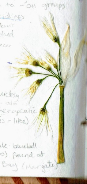
One of the major toxic compounds present in bluebells are polyhydroxylated pyrrolidines (such as nectrisine) which are found in the viscous sap that seeps out of the plant’s nodding stems. These compounds are analogues of sugar but are actually potent glucosidase inhibitors. Due to its many -OH groups, the mammalian body mistakes nectrisine as a sugar and processes it as such – inadvertantly allowing the molecule to interfere with respiration.

In addition to this, polyhydroxylated pyrrolizidines, which have a similar chemical action to nectrisine, are toxic alkaloids that have been proven to poison livestock that have the misfortune of ingesting bluebells. Despite this, these compounds are now being considered for use in cancer therapeutics.

Most fascinatingly, bluebells contain a type of cardiac glycoside, Scillaren A, which can rapidly increase the output force of the heart. Heart cells, myocytes, contain protein pumps embedded in their cell membranes which actively transport sodium ions out of the cell to create an essential electrochemical gradient. In the heart, there is also a sodium – calcium ion exchanger which maintains the ion homeostasis. 

Cardiac glycosides, such as Scillaren A found in bluebells, inhibit the movement of sodium ions out of the cell by effectively disabling the ion pumps. This increases the concentration of sodium ions inside the myocytes which, in turn, increases the calcium ion concentration as sodium ions inside the cell are exchanged for calcium ions.

In myocytes, the accumulation of calcium increases the power with which the cells can contract (contractility) – increasing cardiac muscle contraction which can be crucial in controlling the heart rate in cases of arrhythmia and even chemically restarting the heart in atrial fibrillation.

The cardiac action of Scillaren A is stronger than that of the commonly used digoxin, which is derived from foxglove, and is ideal for situations in which digoxin alone is insufficient or the patient has a digitalis intolerance. Additionally, if an improper dosage is administered, Scillaren A is poisonous but, unlike many other cardiac glucosides, is non-lethal as it is poorly absorbed into the gut. The compound also has a very high therapeutic index as it is rapidly eliminated from the body. All of these qualities make bluebells a fundamentally desirable pharmaceutical source, however, since native bluebells are an endangered and protected species, bluebells cannot be harvested to produce medication.

bee - Edited (1)

Conservation efforts are essential to protect and preserve this fragile, flowering species so that we may be able to enjoy their magnificent appearance and benefit from their therapeutic value in the coming decades.


* White bluebells which lack pigmentation also exist albeit they are somewhat rare with only 1 in every 1000 native bluebells being white. Below is a pressed white bluebell I came across in Margate. bluebell - Edited (2) (1)

Dandelion: Taraxacum Officinale

Standard

[This posts features my original botanical sketches]

For me, the most marvellous manifestations of spring are the bright dandelions emerging from previously barren, frost-glazed soil – bringing promises of brighter days to come.  The humble dandelion is so often maligned as a weed, however these perennial plants have a rich therapeutic history.

dandelion - Edited (2) (1)

Nearly half a millennium ago, Nicolas Culpeper, a prominent herbalist of the early 1600s, noted that the dandelion has “an opening and cleansing quality” and remarked upon its efficacy at treating liver ailments (including cirrhosis) as well as diseases of the spleen and gall-bladder. Many of Culpeper’s contemporaries, and indeed modern herbalists, also acknowledge the powerful diuretic properties of dandelion leaves and root.

Dandelions have even proven valuable in cutting-edge pharmaceuticals. Researchers from the Department of Chemistry and Biochemistry at the University of Windsor, Canada,  have found that dandelion root extract can efficiently kill certain types of aggressive leukaemia cells. This extract can induce apoptosis (programmed cell death) and autophagy (wherein the cancer cell breaks down its own organelles), and even disrupt mitochondrial membranes. The lack of toxins and alkaloids in the plant, combined with the extract’s selectivity for leukaemia cells, makes the dandelion a particularly promising candidate for safe chemotherapy applications.


Ovadje, P., Hamm, C., & Pandey, S. (2012). Efficient induction of extrinsic cell death by dandelion root extract in human chronic myelomonocytic leukemia (CMML) cells. PloS one7(2), e30604. doi:10.1371/journal.pone.0030604

https://www.ncbi.nlm.nih.gov/pmc/articles/PMC3281857/


Visual Prosthesis : Latest Innovations

Standard

The face of biotechnology is constantly evolving; blink and you’ll miss it. Latest developments in visual prosthesis are bringing us one step closer to the miracle of restoring sight to the blind.

Over a year ago, I blogged about one of my many visits to the Wellcome Museum in London and, in particular, my interest in the glass eye collection of W. Halford (1870-1920). Curiosity had compelled me to further research the history of ocular prosthetic devices. One of the earliest ocular prostheses dates back to 2900–2800 BCE and serves a purely aesthetic purpose with its radiant “gold lines patterned like sun rays”.

Modern ocular prostheses have become safer and more lifelike. They are typically made of medical grade plastic acrylic in order to avoid issues such as shattering of the prosthetic in the eye. Realism of artificial eyes have been continually developing since the first ocular prosthesis; the main limitation being realistic pupil movement. Ocularists and eye surgeons have always worked together to make artificial eyes look more realistic. For decades, all efforts and investments to improve the appearance of artificial eyes have been dampened by the immobility of the pupil. The most recent solution to this issue is to use an LCD display to vary the pupil size depending on the light intensity of the environment. Despite these large strides forward in the aesthetic qualities and features of ocular prosthetic devices, until very recently, such devices have not offered the most valuable feature of all: vision.

Last night, in the most recent issue of the National Geographic which focuses on the future of medicine, one article in particular caught my eye; researchers have made the possibility of a true bionic eye tangible through 3D printing.

The concept of electrically stimulating the visual cortex and retina to produce artificial sight first surfaced in the 18th century, however (due to technological and anatomical difficulties) this concept is only reaching actualisation within the past decade. The retina  contains light detecting cells called photoreceptors which convert light energy  stimuli into electrical energy for transmission to the brain. In most cases, blindness is caused by the death of these photoreceptors as opposed to the transmission nerve cells that respond to stimuli and send messages to the brain. While those nerve cells cannot detect light on their own, they can respond to electrical stimulation; this is what much of the research into visual prosthesis is focused on.

The Argus II Retinal Prosthesis (patented in 2011) is the first of such devices to receive FDA approval; it consists of a camera mounted onto eyeglass frames which is connected to a processor and retinal impant containing 60 miniscule electrodes. Although certainly a blessing to patients who have been able to regain sight with this prosthesis, the Argus II is far from a natural bionic eye.

             second-sight-glasses  argus-ii


The  latest reported prototype of the bionic eye (developed by researchers from the University of Minnesota in August 2018) has an uncanny realism and functionality that I found entirely fascinating. The bionic eye has a 25% efficiency in converting light into electrical signals thanks to its semiconducting polymer photodiodes which cover a 3D printed base of silver particles lining the interior of the hemispherical glass dome. This prototype represents a milestone in the field; it proves that semiconducting materials can be ‘printed’ onto curved surfaces and, more importantly, that such devices can be cost-effective- designed by a humble 3D printer in under a hour as opposed to in high-tech microfabrication labs.

bionic-eye-1400x600-770x494.png

Beautiful as it is, this bionic eye still needs further development to make the surface softer and more suitable for implantation and to improve light conversion efficiency. Within another decade, such devices should be available as true cures to blindness- perhaps the future isn’t so dark after all…


Work Experience: Centre for Liver Research, University of Birmingham

Standard

Over the course of the two weeks of my work experience, I had the opportunity to try out new laboratory techniques and to explore various aspects of the research being done at the University of Birmingham, Centre for Liver Research. In this account I will focus solely on the major highlights (despite each day having been amazing and enriching in its own right).

On the first day, I was greeted warmly by Dr Zania Stamataki and given a tour of the Medical School building and the IBR building. We discussed about the research being done by her team concerning hepatocytes and their interaction with the immune system (mainly CD4+ T-cells). Having completed a FutureLearn course on the liver (Liver Disease: Looking after Your Liver – University of Birmingham) provided me with a decent background to understanding the fascinating concepts Zania introduced me to. I learnt the basics of cell-in-cell structures and the vital efferocytosis that hepatocytes perform and what these processes mean for inflammation and the development of cancer and metastasis.

In the afternoon, Janine Fear lead an induction in which I was exposed to the many fascinating laboratories and ‘behind-the-scene’ areas such as the waste disposal and incineration systems, the autoclave room, and the liquid nitrogen cooling systems. One of the many surprising things I was shown was the autoclave tape – I couldn’t help but marvel at the simple yet ingenious concept of tape that changes colour when exposed to the high temperatures of the sterilisation process. Janine Fear also informed me of the lab safety procedures and that the labs I would be working in are classed as Category 2 and that the majority of the labs are fitted with Class II biosafety cabinets. As part of the induction, Janine also taught me basic skills (such as how to use a micropipette and a pipette gun) which I later utilised when performing experiments.

After the induction, I was introduced to Adam McGuinness (a PhD student) who showed me several culture flasks (containing hepatocytes and T-cells) under a light microscope. He also explained that the nutrient medium provided to the cells contains an indicator which changes to yellow as the solution becomes acidic (because CO2 is produced as the cells metabolise) – indicating that the medium should be changed. I recalled that a similar process was used by the BactAlert machines in the serology lab in Mumbai (where I shadowed Dr Salunke last year); the machine detected low pH of blood cultures (which indicates sepsis: bacteria in the blood produce CO2 – making the blood acidic). The hepatocytes cultured in this lab were from a cancer cell line (Huh7) – I learnt that cell lines are ideal for research as they can survive and replicate better than primary cells in vitro.

On day two, Zania and I discussed the role of a researcher and the many facets of the job (including the process of writing and revising publications and some aspects of what makes for a high-impact publication worthy of a renowned journal such as Cell or Nature). Our discussion then drifted back to Zania’s current research and she explained to me that the host cells of cell-in-cell structures can fail to divide as the cell inside them becomes a physical obstruction to cytokinesis. Fascinated by this concept, I spent the rest of the morning reading publications* on cell-in-cell structures which Zania recommended to me (including one written by her former PhD student, Alex Wilkinson).

In the afternoon, I observed Adam performing an experiment to image a host cell hepatocyte failing to divide due to a T-cell inside it. He explained the various fluorescent cell tracker dyes and cytoplasm stains which would be used to image the experiment. We then visited Dr Omar Qureshi who introduced us to the impressive Celldiscoverer 7 (ZEISS) capable of fluorescence microscopy and performing time-lapse imaging.

The next day,  imaging experts from ZEISS explained the process of analysing the images produced by the Celldiscoverer 7; the analysis software can be configured to automatically count the number of cell-in-cell structures and identify any host cells which failed to divide.

Afterwards, I followed Adam to a meeting with the rest of the students who are taking the same PhD course (Sci-Phy). One of the major advantages of shadowing both a student and a PhD supervisor was that I gained exposure to the many aspects of completing a PhD course (such as writing a thesis and preparing for a viva) from different perspectives. During this meeting, Adam presented his plans for a mini-project which involved using machine learning to identify and quantify cell-in-cell structures.

In the afternoon, I attended an interesting lecture (presented by Alejandra Tomas from Imperial College) with Zania regarding current research into improving pancreatic beta cell function.

On the fourth day, I had the very exciting chance to do some ‘hands-on’ work; under the direction of Zania, I ‘split’ a cell culture of hepatocytes. Since the hepatocytes are from a cancer cell line, they can be repeatedly ‘split’ to allow them to proliferate and be used for various experiments. It was delightful to have this opportunity which enabled me to sharpen my skills in handling pipettes and working with the hepatocytes. I also learnt how to care for the surfaces and machines in the lab; I cleaned all the worktops in the labs with 70% IMS (Industrial Methylated Spirit) and Trigene before commencing my work, which ensures that the surfaces are sterile.

The afternoon provided another opportunity to immerse myself further in the topic of cell-in-cell structures and I read two absorbing publications: ‘Cell-in-cell phenomena, cannibalism, and autophagy’ and ‘Entosis enables a population response to starvation’. I found the latter article intriguing as it introduced the idea of host cells obtaining nutrients and biomass through phagocytosis of neighbouring cells as part of a coordinated response to long-term glucose starvation.

On day five, I observed Adam perform another experiment which explored the relationship between the number of necrotic T-cells provided to hepatocytes and the number of phagocytosis events (in which cell-in-cell structures are formed). The experiment used serial dilutions of necrotic T-cells; hepatocytes can engulf dead T-cells easily (even in low quantities).  Following this, we imaged the experiment using the smaller, yet equally impressive, CX5 fluorescence microscope.

In the afternoon, we analysed the images from this experiment to yield averages for the number of cell-in-cell structures observed with the different concentrations of T-cells. I performed some manual counts with the help of an image editing software (Image J) whilst Adam began to use Matlab (a programming language) to automate this process.

On the first day of my second week with the University of Birmingham, I attended a conference with Zania (who chaired the third session) on stromal microenvironments in health and disease. A variety of speakers from the University of Birmingham (and a plenary speaker from Barts Cancer Institute) presented their research on a vast range of topics connected to stromal cells (cells that make up the supporting tissue of organs) from potential cures for rheumatoid arthritis (presented by Andrew Filer) to identifying indicators of myeloma and hallmarks of cancer (presented by Dan Tenant). These presentations helped to further enhance my understanding of the incredible research undertaken at the University of Birmingham.

Two days later, I had the pleasure of meeting visiting Professor Lucie Peduto from the Pasteur Institute. Her research lab has a strong focus on stroma which relates to the liver stromal microenvironment researched here. In the afternoon, I attended her seminar on the relationship between stromal cells, fibrosis, and cancer; having attended the conference on stromal microenvironments earlier that week allowed me to gain a better understanding of her research.

The penultimate two days of my work experience were by far my favourite; I had the exciting opportunity to perform an entire experiment single-handedly. My detailed observation of the experiments performed by Adam proved very useful as I performed the same experiment he did on day five (which explored the relationship between the number of necrotic T-cells provided to hepatocytes and the number of phagocytosis events).  It felt like a culmination of all my training and learning from the past two weeks and I utilised all the skills I had learnt by shadowing and observing Adam performing experiments. In the morning of my ninth day at the University of Birmingham, I observed the cells I had split and cultured the previous Thursday and was pleasantly surprised to find that they were thriving and ready to use for the experiment. Completing this experiment helped me to develop my organisational skills as I carefully followed the protocol Adam had created and balanced different tasks simultaneously.

Overall, my work experience at the University of Birmingham has been a fantastic experience and I am extremely grateful to Dr Zania Stamataki and Adam McGuinness for teaching and supporting me throughout my time here.

me


* I have provided the list of publications I had the pleasure of reading in case you would also like to immerse yourself into this fascinating field:

The Chemistry of Communication

Image

Action_potential_propagation_animation

This brilliant gif, created by John Schmidt, summarises how ions cause changes in voltage that allow electrical signals to be propagated down axons. The accompanying explanation of the gif clarifies the many factors at play here:

Three types of ion channel are shown: potassium “leak” channels (blue), voltage-gate sodium channels (red) and voltage-gated potassium channels (green). The movement of positively-charged sodium and potassium ions through these ion channels controls the membrane potential of the axon.

The negative-inside resting potential is mostly determined by potassium ions leaving the cell through leak channels. Action potentials are initiated in the axon initial segment after a neurotransmitter activates excitatory receptors in the neuron’s dendrites and cell body.

This depolarizes the axon initial segment to the threshold voltage for opening of voltage-gated sodium channels. Sodium ions entering through the sodium channels shift the membrane potential to positive-inside, approaching the sodium equilibrium potential.

The positive-inside voltage during the action potential in the initial segment causes the adjacent part of the axon membrane to reach threshold. When positive-inside membrane potentials are reached, voltage-gated potassium channels open and voltage-gate sodium channels close.

Potassium ions leaving the axon through voltage-gated potassium channels return the membrane potential to negative-inside values near the potassium equilibrium potential. When the voltage-gated potassium channels gate shut, the membrane potential returns to the resting potential.

(Credit: Wikiversity)


This post  is part of the Neuroscience Crash Course (a mini series about the brain created in preparation for the Brain Bee) and is a further clarification of A Closer Look at Neurons – I would strongly recommend reading that post before this one.